No Factory personal needed for installation. Please read the installation manual in full before assembly on site.
Mounts to fit: 1-1/2″ OD to 3-1/2″ OD (38-89 mm) outrigged pole (supplied by customer).
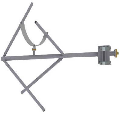
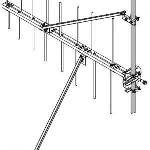
Installation & Mounting Layout
Model 6832 Antenna Weight & Wind Load
Weight Full-wave Spaced
| No. of Bays | Vertical Tower Space | Weight |
| Antenna Radiation Aperture | Pipe Length Required | Total tower space
recommended | Without ice | With
1/2" (1.2 cm) radial ice | With
1" (2.5 cm) radial ice | With
2" (5.1 cm) radial ice |
| ft | m | ft | m | ft | m | lb | N | lb | N | lb | N | lb | N |
| 1 | 4.1 | 1.25 | 10 | 3.05 | 20 | 6.1 | 38 | 169 | 63 | 280 | 99 | 663 | 144 | 651 |
| 2 | 8.2 | 2.5 | 18.5 | 5.6 | 28.2 | 8.6 | 79 | 351 | 145 | 645 | 244 | 1085 | 375 | 1668 |
| 3 | 16.3 | 5 | 26.4 | 8.05 | 36.4 | 11.1 | 106 | 471 | 215 | 956 | 385 | 1712 | 615 | 2735 |
| 4 | 24.5 | 7.5 | 34.5 | 10.5 | 44.5 | 13.6 | 140 | 623 | 284 | 1263 | 507 | 2255 | 811 | 3607 |
| 5 | 32.7 | 10 | 42.7 | 13.01 | 52.7 | 16.06 | 173 | 740 | 374 | 1663 | 695 | 3091 | 1138 | 5062 |
| 6 | 40.8 | 12.43 | 50.8 | 15.48 | 60.8 | 18.53 | 198 | 881 | 438 | 1948 | 821 | 3652 | 1348 | 5996 |
| 8 | 57.2 | 17.43 | 67.2 | 20.48 | 77.2 | 23.53 | 280 | 1245 | 640 | 2847 | 1230 | 5471 | 2049 | 9114 |
Windload Full-wave Spaced
| No. of Bays | Without ice | With 1/2" (1.2 cm) radial ice | With 1" (2.5 cm) radial ice | With 2" (5.1 cm) radial ice |
| EPAN | EPAT | EPAN | EPAT | EPAN | EPAT | EPAN | EPAT |
| ft2 | m2 | ft2 | m2 | ft2 | m2 | ft2 | m2 | ft2 | m2 | ft2 | m2 | ft2 | m2 | ft2 | m2 |
| 1 | 2.4 | 0.22 | 1.2 | 0.11 | 3.3 | 0.31 | 1.7 | 0.16 | 4.1 | 0.38 | 2.2 | 0.20 | 5.0 | 0.46 | 2.9 | 0.27 |
| 2 | 6.5 | 0.60 | 4.1 | 0.38 | 10.3 | 0.96 | 7.0 | 0.65 | 13.8 | 1.28 | 10.0 | 0.93 | 17.4 | 1.62 | 13.1 | 1.22 |
| 3 | 10.5 | 0.98 | 6.9 | 0.64 | 18.1 | 1.68 | 13.3 | 1.24 | 25.4 | 2.36 | 19.7 | 1.83 | 32.7 | 3.04 | 26.3 | 2.44 |
| 4 | 13.9 | 1.29 | 9.1 | 0.85 | 24 | 2.23 | 17.5 | 1.63 | 33.6 | 3.12 | 26.1 | 2.42 | 43.3 | 4.02 | 34.9 | 3.24 |
| 5 | 19.2 | 1.78 | 13.2 | 1.23 | 35.2 | 3.27 | 27.1 | 2.52 | 50.7 | 4.71 | 41.3 | 3.84 | 66.2 | 6.15 | 55.6 | 5.17 |
| 6 | 22.9 | 2.13 | 15.7 | 1.46 | 42.0 | 3.90 | 32.2 | 2.99 | 60.4 | 56.1 | 49.1 | 4.56 | 78.9 | 7.33 | 66.3 | 6.16 |
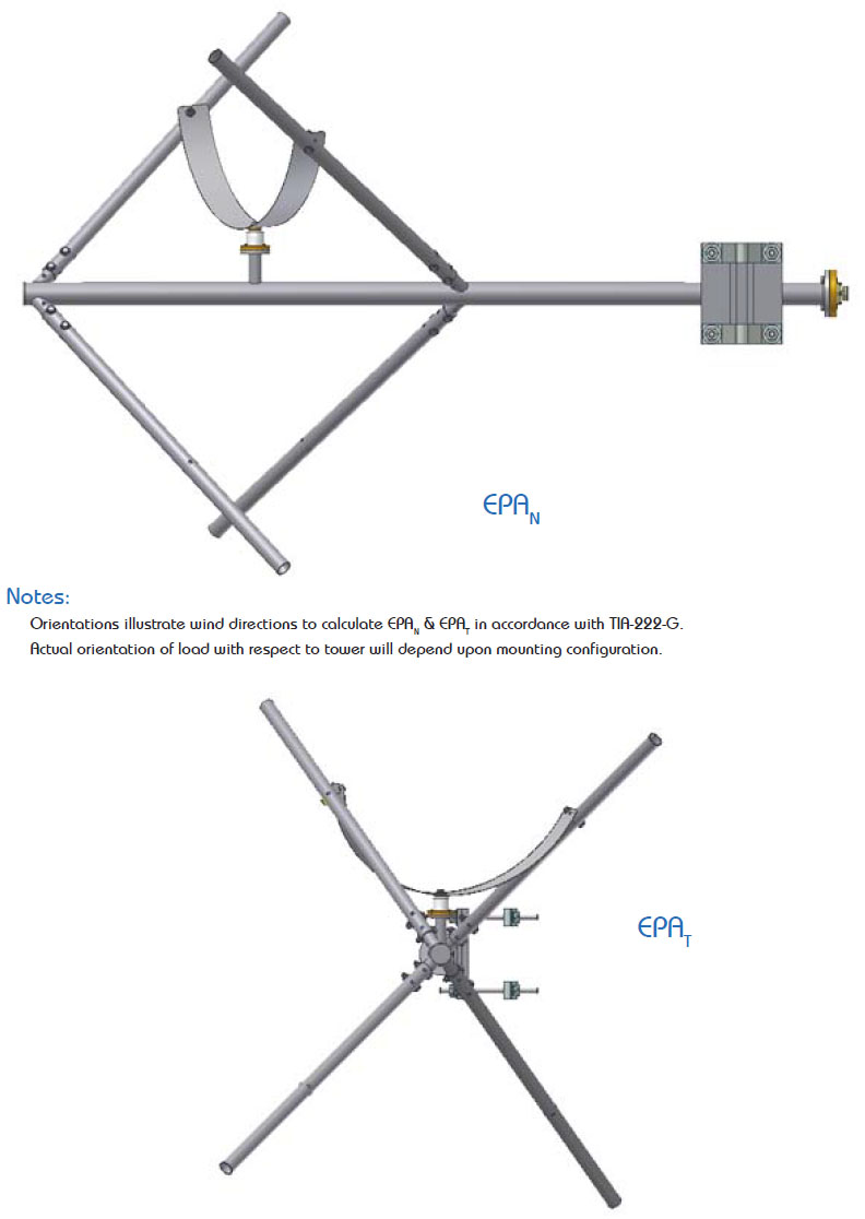
Notes:
WINDLOAD TABLE(S)
1. Antenna radiation aperture is the distance from the center of the top bay to the center of the bottom bay. Five feet (1.5 m) of the pipe is required above the top of the top bay and below the bottom bay. Total tower space recommended allows ten feet (3 m) of clear tower space above the center line of the top bay and below the center line of the bottom bay, to protect from pattern interference by other antennas. At frequencies lower than 98 MHz, each of these dimensions will increase by up to 1 foot (0.3 m) per bay.
2. Windload and weight tabulations assume full-wave bay spacing and include the bay, mounts and interbay feedline.
3. Antenna areas and weights calculated in accordance with TIA-222-G. EPA(N) – Effective projected area associated with the windward face normal to the azimuth of the antenna: EPA(N) = (Ca AA )N EPA(T) – Effective projected area associated with the windward face at the side of the antenna: EPA(T) = (Ca AA )T Assumptions: Structure Class II; Exposure category C; Topographic category 1; Maximum basic windspeed 90 mph; with 1/2 inch design ice, 40 mph; Maximum height above ground 200 ft.
4. Ask for technical assistance at Shively if you are planning to mount antennas on AM towers or install them at altitudes over 3,000 ft (915 m) above mean sea level.

Reviews
There are no reviews yet.