No Factory personal needed for installation. Please read the installation manual in full before assembly on site.
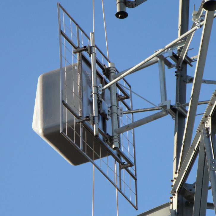
Installation & Mounting Layout
Model 6014 Antenna Weight & Wind Load
Size & Weight Full-wave Spaced
No. of Levels
(3 panels each) | Vertical Tower Space | Weight |
| Antenna Radiation Aperture | Without Ice | With 1/2" (1.2 cm) radial ice |
| ft | m | lb | N | lb | N |
| 1 | 10 | 3.1 | 630 | 2802 | 1387 | 6170 |
| 2 | 20 | 6.1 | 1086 | 4831 | 2388 | 10622 |
| 3 | 30 | 9.1 | 1541 | 6855 | 3390 | 15079 |
| 4 | 40 | 12.2 | 1996 | 8879 | 4392 | 19536 |
| 6 | 60 | 18.3 | 2907 | 12931 | 6395 | 28446 |
| 8 | 80 | 24.4 | 3818 | 16983 | 8399 | 37360 |
| 10 | 100 | 30.5 | 4728 | 21031 | 10402 | 46270 |
| 12 | 120 | 36.5 | 5639 | 25083 | 12406 | 55184 |
Windload Full-wave Spaced
No. of Levels
(3 panels each) | Revision 'C' | Revision 'F' |
| Without Ice | With 1/2" (1.2 cm) radial ice | Without Ice | With 1/2" (1.2 cm) radial ice |
| lb | kg | lb | kg | ft2 | m2 | ft2 | m2 |
| 1 | 1022 | 4581 | 2372 | 10631 | 33 | 3.1 | 67 | 6.2 |
| 2 | 2044 | 9161 | 4743 | 21258 | 65 | 6.0 | 135 | 12.5 |
| 3 | 3066 | 13742 | 7115 | 31889 | 98 | 9.1 | 202 | 18.8 |
| 4 | 4088 | 18322 | 9486 | 42516 | 130 | 12.1 | 270 | 25.0 |
| 6 | 6132 | 27484 | 14229 | 63774 | 196 | 18.2 | 405 | 37.6 |
| 8 | 8176 | 36645 | 18972 | 85033 | 261 | 24.2 | 539 | 50.1 |
| 10 | 10220 | 45806 | 23715 | 106291 | 326 | 30.3 | 674 | 62.6 |
| 12 | 12264 | 54967 | 28458 | 127549 | 391 | 36.3 | 809 | 75.2 |
| | | | | | | | |
| | | | | | | | |
| | | | | | | | |
| | | | | | | | |
Notes:
WINDLOAD TABLE(S)
1. Standard mounts are designed to fit customer-supplied 1-1/4″ ips (1.5″ OD) – 3″ pipe (3.5″ OD) pole or tower leg.
2. Windload and weight tabulations are estimates and assume 98 MHz. No values are included for mounts. The values for mounts, complex feed systems and directional arrays may significantly affect these estimates. Shielding due to the tower has not been accounted for. Please contact the factory for an estimate for a system to meet your specific requirements.
3. Antenna areas and weights calculated in accordance with TIA-222-G.
- EPAN – Effective projected area associated with the windward face normal to the azimuth of the antenna: EPAN = ∑(CaAA)N
- EPAT – Effective projected area associated with the windward face at the side of the antenna: EPAT=∑(CaAA)T
- Assumptions: Structure Class II; Exposure Category C; Topographic Category 1; Maximum basic windspeed 120 mph; with 1/2 inch radial ice, 40 mph.
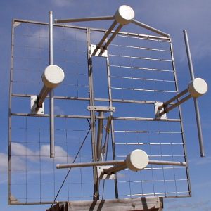
4. Elements can be stacked or arrayed for omni or directional patterns.
5. System designed for maximum of 2″ factored radial ice (tis) at height using TIA-222-G specifications and maximum velocity pressure of 51.29 lbf/ft2 with no ice.
6. Ask for technical assistance at Shively if you are planning to mount antennas on AM towers or install them at altitudes over 3,000ft (915m) above mean sea level.
Reviews
There are no reviews yet.