No Factory personal needed for installation. Please read the installation manual in full before assembly on site.
Installation & Mounting Layout
Dual Setting Thermostat Install Sheet
Model 6602 Antenna Weight & Wind Load
Size & Weight Full-wave Spaced
| No. of Bays | Vertical Tower Space | Weight |
| Antenna Radiation Aperture | Physical Space Used | Total Tower Space Recommended | Without radomes | With radomes | With radomes & 1/2" (1.2 cm) radial ice |
| ft | m | ft | m | ft | m | lb | N | lb | N | lb | N |
| 1 | 2.0 | 0.6 | 12.0 | 3.7 | 22.0 | 6.7 | 3 | 13 | 38 | 169 | 57 | 254 |
| 2 | 8.5 | 2.6 | 18.5 | 5.6 | 28.5 | 8.7 | 10 | 45 | 80 | 357 | 122 | 544 |
| 3 | 17.0 | 5.2 | 27.0 | 8.2 | 37.0 | 11.3 | 17 | 76 | 122 | 544 | 187 | 834 |
| 4 | 25.5 | 7.8 | 35.5 | 10.8 | 45.5 | 13.9 | 23 | 103 | 163 | 727 | 252 | 1124 |
| 5 | 34.0 | 10.4 | 44.0 | 13.4 | 54.0 | 16.5 | 30 | 134 | 205 | 914 | 317 | 1414 |
| 6 | 42.5 | 13.0 | 52.5 | 16.0 | 62.5 | 19.1 | 37 | 165 | 247 | 1102 | 382 | 1704 |
| 7 | 51.0 | 15.5 | 61.0 | 18.6 | 71.0 | 21.6 | 43 | 192 | 288 | 1284 | 447 | 1994 |
| 8 | 59.5 | 18.1 | 69.5 | 21.2 | 79.5 | 24.2 | 50 | 223 | 330 | 1472 | 513 | 2288 |
Windload Full-wave Spaced
| No. of Bays | Revision 'C' | Revision 'F' |
| Without Radomes | With Radomes | With Radomes & 1/2" (1.2 cm) radial ice | Without Radomes | With Radomes | With Radomes & 1/2" (1.2 cm) radial ice |
| lb | kg | lb | kg | lb | kg | ft2 | m2 | ft2 | m2 | ft2 | m2 |
| 1 | 5 | 22 | 66 | 294 | 73 | 326 | 0.2 | 0.0 | 1.7 | 0.2 | 1.9 | 0.2 |
| 2 | 13 | 58 | 134 | 598 | 153 | 682 | 0.4 | 0.0 | 3.5 | 0.3 | 4 | 0.4 |
| 3 | 20 | 89 | 202 | 901 | 234 | 1044 | 0.6 | 0.1 | 5.4 | 0.5 | 6.3 | 0.6 |
| 4 | 28 | 125 | 270 | 1204 | 315 | 1405 | 0.9 | 0.1 | 7.2 | 0.7 | 8.5 | 0.8 |
| 5 | 35 | 156 | 339 | 1512 | 395 | 1762 | 1.1 | 0.1 | 9 | 0.8 | 10.7 | 1.0 |
| 6 | 42 | 187 | 407 | 1815 | 476 | 2123 | 1.3 | 0.1 | 10.8 | 1.0 | 12.9 | 1.2 |
| 7 | 49 | 219 | 475 | 2119 | 557 | 2484 | 1.5 | 0.1 | 12.6 | 1.2 | 15.1 | 1.4 |
| 8 | 57 | 254 | 543 | 2422 | 637 | 2841 | 1.8 | 0.2 | 14.4 | 1.3 | 17.3 | 1.6 |
Size & Weight Half-wave Spaced
| No. of Bays | Vertical Tower Space | Weight |
| Antenna Radiation Aperture | Physical Space Used | Total Tower Space Recommended | Without radomes | With radomes | With radomes & 1/2" (1.2 cm) radial ice |
| ft | m | ft | m | ft | m | lb | N | lb | N | lb | N |
| 2 | 4.3 | 1.3 | 14.3 | 4.3 | 24.3 | 7.4 | 10 | 45 | 80 | 357 | 122 | 544 |
| 3 | 8.5 | 2.6 | 18.5 | 5.6 | 28.5 | 8.7 | 17 | 76 | 122 | 544 | 187 | 834 |
| 4 | 12.8 | 3.9 | 22.8 | 6.9 | 32.8 | 10.0 | 23 | 103 | 163 | 727 | 252 | 1124 |
| 5 | 17.0 | 5.2 | 27.0 | 8.2 | 37.0 | 11.3 | 30 | 134 | 205 | 914 | 317 | 1414 |
| 6 | 21.3 | 6.5 | 31.3 | 9.5 | 41.3 | 12.6 | 37 | 165 | 247 | 1102 | 382 | 1704 |
Windload Half-wave Spaced
| No. of Bays | Revision 'C' | Revision 'F' |
| Without Radomes | With Radomes | With Radomes & 1/2" (1.2 cm) radial ice | Without Radomes | With Radomes | With Radomes & 1/2" (1.2 cm) radial ice |
| lb | kg | lb | kg | lb | kg | ft2 | m2 | ft2 | m2 | ft2 | m2 |
| 2 | 1.3 | 58 | 134 | 598 | 153 | 682 | 0.4 | 0.0 | 3.5 | 0.3 | 4 | 0.4 |
| 3 | 20 | 89 | 202 | 901 | 234 | 1044 | 0.6 | 0.1 | 5.4 | 0.5 | 6.3 | 0.6 |
| 4 | 28 | 125 | 270 | 1204 | 315 | 1405 | 0.9 | 0.1 | 7.2 | 0.7 | 8.5 | 0.8 |
| 5 | 35 | 156 | 339 | 1512 | 395 | 1762 | 1.1 | 0.1 | 9 | 0.8 | 10.7 | 1.0 |
| 6 | 42 | 187 | 407 | 1815 | 476 | 2123 | 1.3 | 0.1 | 10.8 | 1.0 | 12.9 | 1.2 |
Notes:
WINDLOAD TABLE(S)
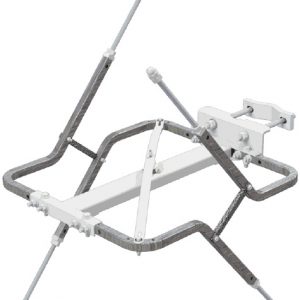
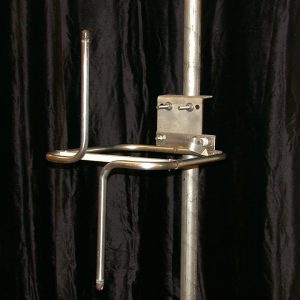
1. Standard mounts are designed to fit customer-supplied 2″ pipe (2
3/8″ OD) – 3″ pipe (3 1/2″ OD) pole or tower leg.
2. Weight, windload, and space tabulations assume 98 MHz and include the bay, interbay feedline, input connection, and standard
mounting brackets.
3. Antenna windloads are calculated for 112 mph (180 kph), using 50 psf (2400 N/m2) for flats and 33 psf (1600 N/m2) for rounds]
per EIA standard RS-222-C and CSA standard S37-94. The surface area is calculated per EIA standard RS-222-F (CaAc).
4. Antennas with two bays or an odd numbers of bays are end-fed; antennas with even numbers of bays are center-fed.
5. Deicers add approximately 1 lb (4.4 N) per bay in weight and 2 lb (8.9 N) or 0.3 ft2 (0.028m2) per bay in windload.
6. Ask for technical assistance at Shively if you are planning to mount antennas on AM towers or install them at altitudes over 3,000ft (915m) above mean sea level.

Reviews
There are no reviews yet.